Command Details: Expected_Ident_Ind
Category
Extended
Details
Command Code: | 1Bh |
Valid for: | Object Instance |
Description
The module issues this command to inform the host application of the Expected Identification (Module/Submodule List) that the IO Controller will use for the established AR.
Note that this information may be split in multiple segments, which means that this command will be issued multiple times by the module, each time containing different parts of the configuration.
Expected_Ident_Ind is similar to AR_Info_Ind but uses a different segmentation protocol that shall be used for the 40 series concept, see Anybus CompactCom 40 Software Design Guide (Message Segmentation).
For very large configurations where the Expected Identification cannot fit into one message, this segmentation protocol will be used. If the number of modules/sub-modules exceeds the capabilities of the Anybus CompactCom the message will be truncated. The size of the configuration can be up to 2370 bytes at maximum number of modules/sub-modules.
It is optional to implement support for this command.
Command Details
Field
Contents
Comments
CmdExt[0]
Reserved
For segmented messages the CmdExt[1] byte has been reserved for segment bits, see Anybus CompactCom 40 Software Design Guide (Message Segmentation)..
CmdExt[1]
Cmd segment bits
MsgData[0]
AR handle (low byte)
Handle for the Application Relationship.
MsgData[1]
AR handle (high byte)
MsgData[2.. n]
Data field
The first two bytes in the initial block of the Data field indicates the number of modules in the configuration. Each module is represented by a Module block, followed by a number of Submodule blocks (provided that the module in question contains submodules). See “Data Format” below for coding of the data field.
Response Details
Field
Contents
Comments
CmdExt[0]
Reserved
(set to zero)
CmdExt[1]
MsgData[0]
Continue/Block
Value:
Meaning:
0
Continue. The host application will not perform any changes to the Real Identification, A connect response may be sent on the network immediately following this response.
1
Block. The host application will perform changes in the Real identification in response to the received Expected identification. A connect response will not be sent on the network until Ident_Change_Done is sent by the host application
Returning any error response or providing no data/ too much data will give the ssame result as responding with Continue (0).
The timeout is 300 seconds. A “Continue” response or the Ident_Change_Done command should be sent well within this time limit.
Data Format
When all data has been received, the resulting data shall be interpreted as follows:
Type | Name | Description | |||
|---|---|---|---|---|---|
UINT16 | iNbrApi | Number of APIs in configuration | |||
UINT32 | iApiNbr | Initial module block including API number and number of module blocks in the API. | |||
UINT16 | iNbrMod | ||||
UINT16 | iSlotNbr | Module block (8 bytes), see below. | |||
UINT16 | iNbrSubMod | ||||
UINT32 | lModIdent | ||||
UINT16 | iSubSlotNbr | Submodule block (10 bytes), see below. | |||
UINT32 | lSubModIdent | ||||
UINT16 | iInDataLength | ||||
UINT16 | iOutDataLength | ||||
The initial API block (iNbrApi) defines the number of APIs in the configuration.
Each API has an initial module block, that includes information on the API number (iApiNbr) and the number of modules (or slots) in the API.
Each module starts with a module block, which holds the slot number, the number of submodules (or subslots) and the module identity number.
Finally each submodule block holds subslot number, submodule identification number, input and output data lengths.
Example
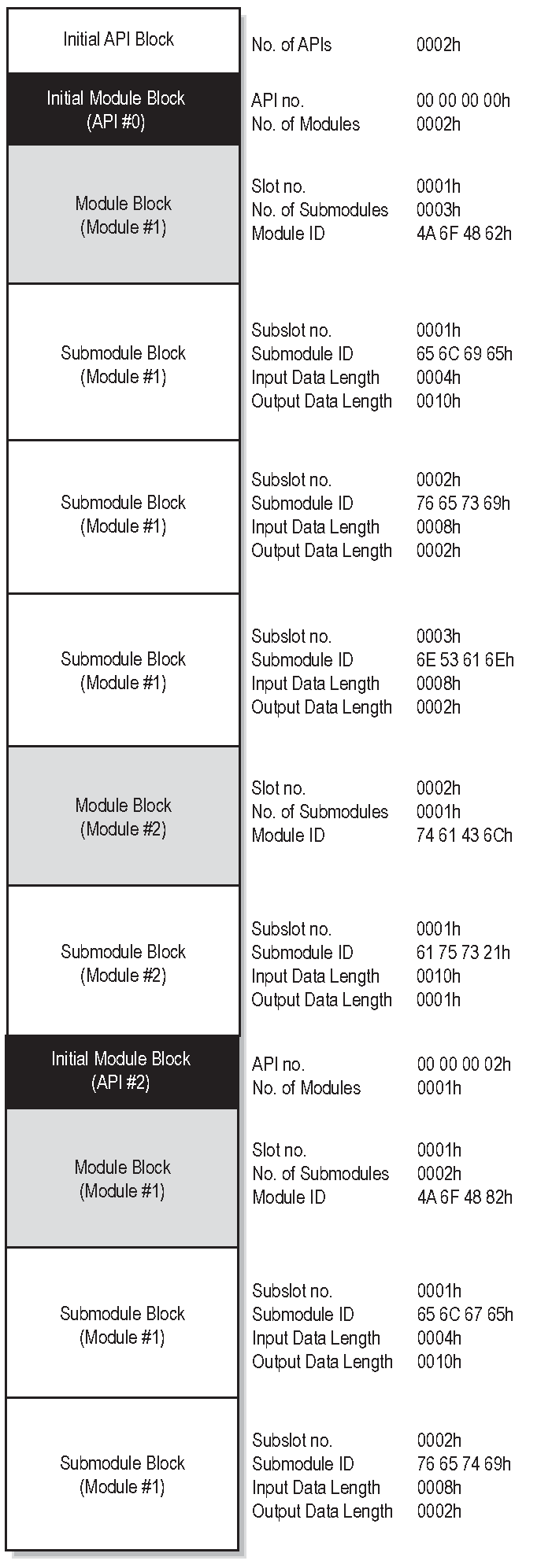
In this example, the configuration contains two APIs with the following properties:
API #0 contains two modules, the first with three submodules, the second with one submodule
API #2 contains one module with two submodules