Transaction Settings
Before You Begin
Note
When a custom transaction is selected, the custom transaction template is locked for editing.
For Modbus transaction reference guide, refer to Modbus Transactions.
 |
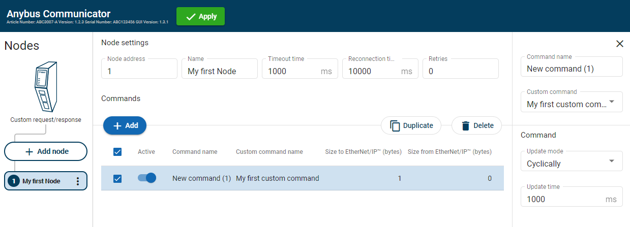 |
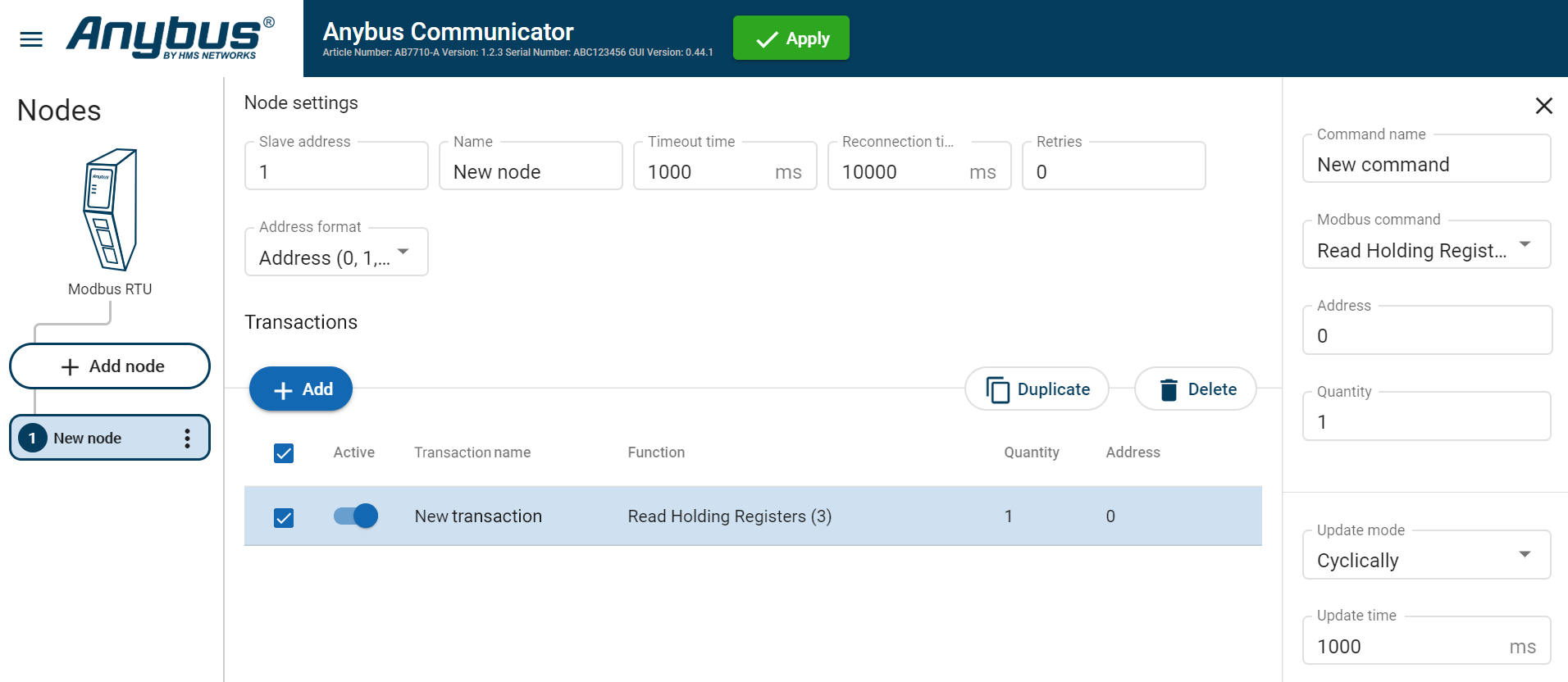
In the node list, select a node to configure.
In the transactions list, select a transaction to configure.
The transactions sidebar opens, on the right side of the screen.
Enter a transaction name.
By default, the node is assigned the name New transaction.
Select a transaction type from the Modbus transaction/Custom transaction drop-down menu.
The transaction type defines what the node should perform when the transaction is executed.
Configure the Command settings.
Setting
Value
Description
Transaction name
N/A
You can name the transaction to make it easier to identify.
Read quantity
1 to 125
Specifies the number of registers to read to follow in the read data field. Appear when Modbus transaction Read Write Multiple Registers (23) is selected.
Address
0 to 65 535
Specify the start address for the read/write transaction.
The address acts as an address to the data position, where the data is read from or written to.
Modbus holding register addresses starts at 0.
Modbus address 0 = Register 1
Write quantity
Read Write Multiple Registers (23), 1 to 123
Specifies the quantity of registers to follow in the write data field. Appear when Modbus transaction Read Write Multiple Registers (23) is selected.
Quantity
Read Holding Registers (3)
Read Input Registers (4), 1 to 125
Write Multiple Coils (15), 1 to 1968
Write Multiple Registers (16), 1 to 123
Read Coils (1)
Read Discrete Inputs (2), 1 to 2000
The Quantity parameter appear when you select a Modbus transaction that can address more than one data object.
Example when Quantity is set: For the Modbus Transaction Read Input Registers (4) you need to set the Quantity in order to define the array of data.
Example when no Quantity is set: For the Modbus Transaction Write Single Coil (5) you do not need to set the Quantity parameter because there can not be an array of data. The transaction is used to write a single output to either ON or OFF in a remote device.
For Write Single Coil (5), Write Single Register (6) and Mask Write Register (22) Quantity cannot be set.
Constant
0 to 255
The value of the Constant in the frame.
Data
0 to 512
The length of the data field.
Variable data
0 to 255
The maximum payload length of the variable data field.
Update mode
Cyclically
On data change Single shot
Change of state on trigger
Specify when a transaction shall be sent to the server. The transaction is issued cyclically, at the interval specified in the Update time parameter.
Cyclically: The transaction is sent cyclically, at the interval specified in the Update time parameter.
On data change: The transaction is sent when the data is changed.
Single shot: The transaction is issued once at start up.
Change of state on trigger: The transaction is triggered when the content of a specified byte changes. In the I/O data map, the node will be marked with a flash icon.In the I/O data map you can also configure the area map and the trigger byte address. See Trigger Byte.
Update time
3 ms to 60 000 ms
Update mode parameter must be set to Cyclically. The Update time parameter appear when Cyclically is select.
Specify how often, in steps of 10 ms, the transaction are going to be issued.
Positive ack
N/A
When Positive Acknowledgement is enabled, the positive ack data byte in the I/O data map is incremented each time this transaction succeeds.
Negative ack
N/A
When Negative Acknowledgement is enabled, the negative ack data byte in the I/O data map is incremented each time this transaction fails.
To apply the settings, click Apply in the web-interface header, and follow the instructions..